HATCH — Hatch
 Ribbon: Draw ▸ Draw ▸ HatchCommand:
HATCHAlias: H, BH
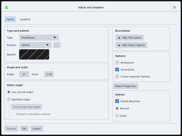
HATCH fills a closed area with a line pattern or a solid colour. The Hatch and Gradient dialog sets the pattern and the area.
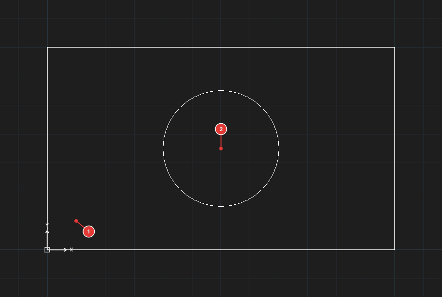
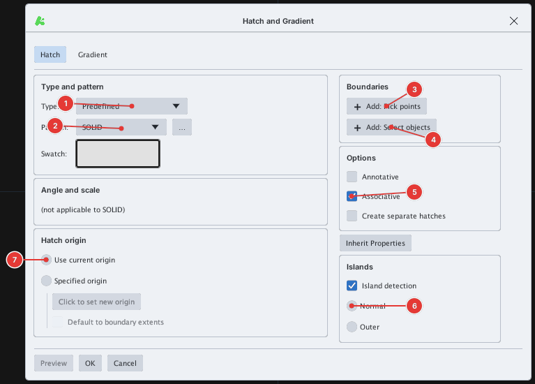
Basic steps
- Type
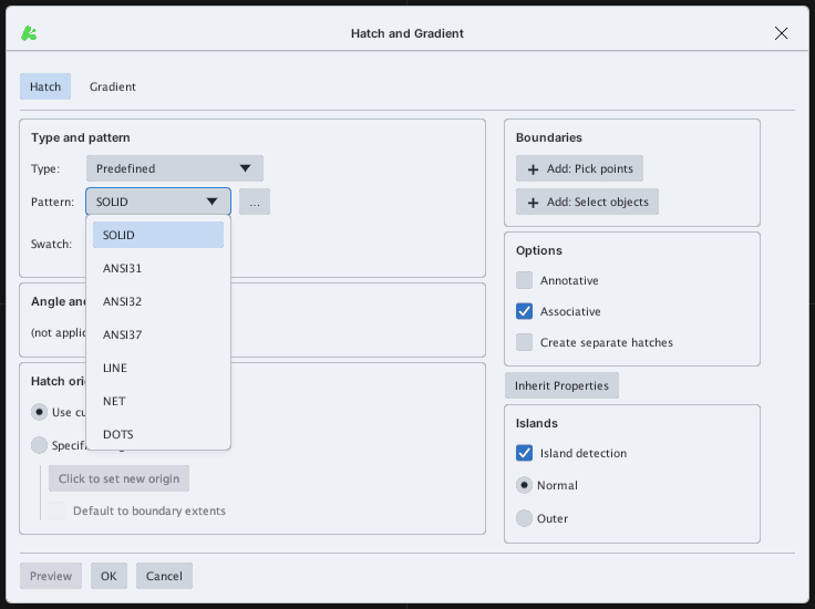
H, Enter (or click the Hatch button) to open the dialog. - Choose Type and Pattern (see below). For line patterns set Angle and Scale.
- Choose the area: Add: Pick points and click a point inside a closed area (
Pick internal point or [Select objects/draW boundary/Undo] <Enter = done>:), or Add: Select objects and pick the boundary objects. - Press Enter when done; the hatch is created (
HATCH: 1 hatch(es) created.). The dialog returns — changing a setting applies at once to the hatch just made; click OK to close.
Type — pattern kind
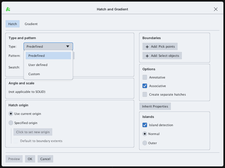
| Type | Description |
|---|---|
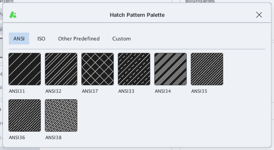
| Predefined | Built-in patterns (ANSI, ISO…). Pick from Pattern or click … to open the palette. |
| User defined | Parallel lines you define: Angle, Spacing and Double (adds crossing lines → a grid). |
| Custom | Patterns from your own .pat file (Load .pat… button). Until a file is loaded the text reads No custom patterns yet. |
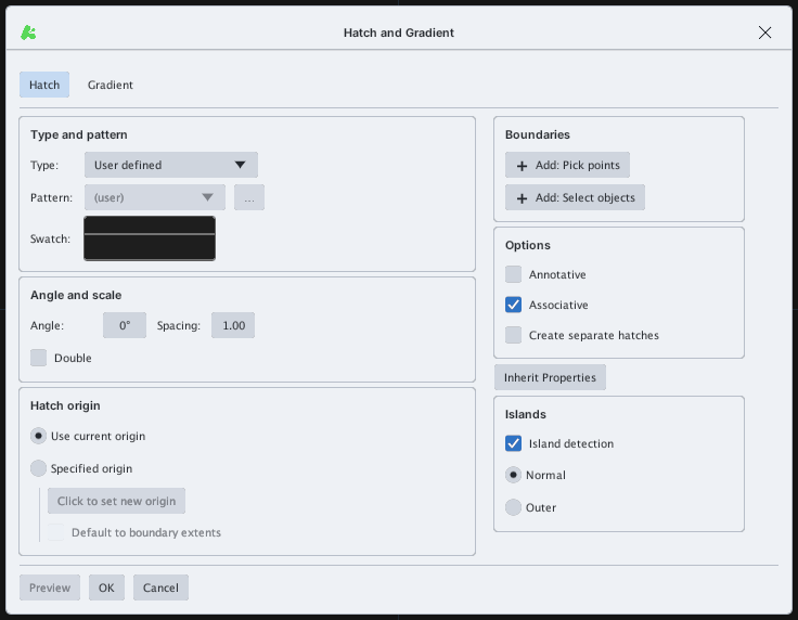
Angle and Scale
Scale multiplies the spacing between pattern lines; Angle rotates the pattern. On millimetre drawings raise Scale (for example 10–30) to open the lines up; the figure above shows scales 10 and 20 of the same ANSI31 pattern.
Islands
An area inside another (such as the round hole) is an island. The Islands group decides how it is filled:
| Setting | Result |
|---|---|
| Island detection bật + Normal | Fill alternates from the outside in: outer area filled, island empty, area inside the island filled again |
| Island detection bật + Outer | Only the outermost area is filled, all islands left empty |
| Island detection tắt (Ignore) | Islands ignored: the fill covers them |
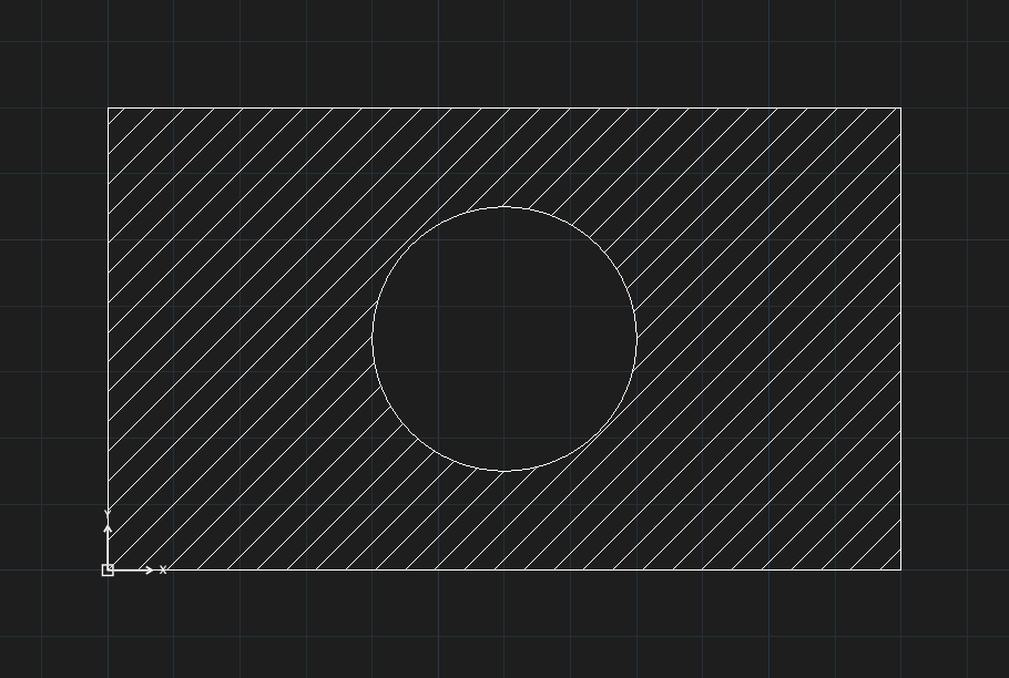
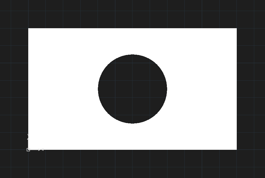
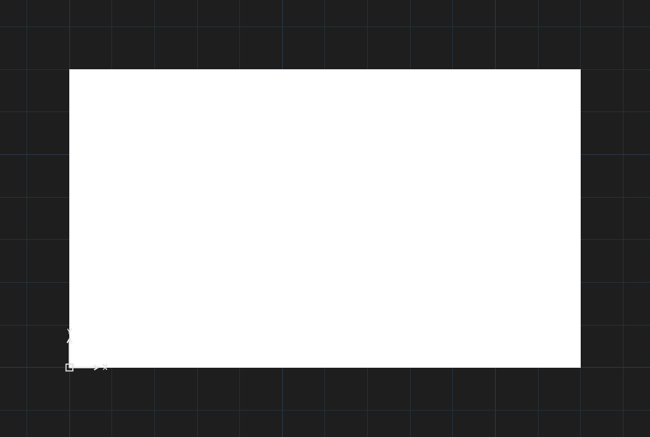
The predefined patterns (ANSI31…) are defined in inches, like AutoCAD's acad.pat; KufCad converts them to the drawing units (UNITS → Insertion scale): millimetre drawings multiply by 25.4 (like acadiso.pat — ANSI31 at scale 1 is 3.175 mm apart), centimetres by 2.54, metres by 0.0254, inches unchanged. The factor is stored on each hatch when it is created (and recovered from the pattern lines when a DWG / DXF is opened), so changing UNITS later does not change existing hatches. User defined patterns use a spacing in drawing units and are not converted.
Hatch origin
Use current origin starts the pattern at the drawing origin; Specified origin lets you click Click to set new origin (Set new hatch origin:) or tick Default to boundary extents.
Other options
| Option | Meaning |
|---|---|
| Annotative | The hatch follows the annotation scale |
| Associative | The hatch follows its boundary: edit the boundary and the hatch updates |
| Create separate hatches | Each picked area becomes its own hatch |
| Inherit Properties | Take pattern, scale and angle from an existing hatch (Select hatch object:) |